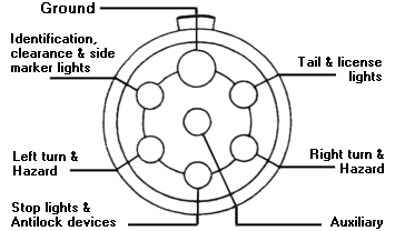
Typical Wiring Diagram For Trailer Lights. Check the wire harness for cuts. Cut anywhere you see a fault, then solder on a new connection, and repair the insulation After you've troubleshot the light wiring system on your trailer, you may find that you need a bit of extra support.

The wires originate from the CECM, here is the diagram.
Typically, these circuits involve automatic pilot devices such as thermostats, float switches, etc.
Assembled control stations are available in a variety of combinations that can include push buttons, selector switches, pilot lights, and special purpose devices. Here is how all components work together to make a typical electrical system Choosing the correct wire size (AWG) is essential for SAFETY (fire hazard due to ampacity ) and PERFORMANCE ( intermittent problems due to voltage drop ) of your electrical system. Cut anywhere you see a fault, then solder on a new connection, and repair the insulation After you've troubleshot the light wiring system on your trailer, you may find that you need a bit of extra support.


